This project involved the meticulous design and analysis of a Reinforced Cement Concrete Underground Water Tank, a critical component of a larger development in a seismically active region. Our approach prioritized structural integrity, code compliance, and cost-efficiency while navigating challenging site conditions.
Project Scope & Key Data
We rigorously applied Indian Standard codes including IS 456, IS 13920, and IS 1893 (Part I) to ensure a robust and safe design. Key considerations included:
Seismic Zone III: Demanding advanced seismic analysis to account for hydrodynamic forces and sloshing.
Challenging Soil Conditions: A low allowable bearing capacity necessitated careful foundation design and uplift checks.
Material Specifications: Utilizing high-grade M30 concrete and Fe415/Fe500/Fe500D HYSD TMT bars for durability.
Tank Dimensions: Designing for specific capacity with overall dimensions of 4.60m (L) x 2.60m (B) x 4.20m (D) for the detailed partition.
Our Design Approach & Solutions
Our methodology combined traditional engineering principles with advanced analytical techniques to address the project’s unique demands.
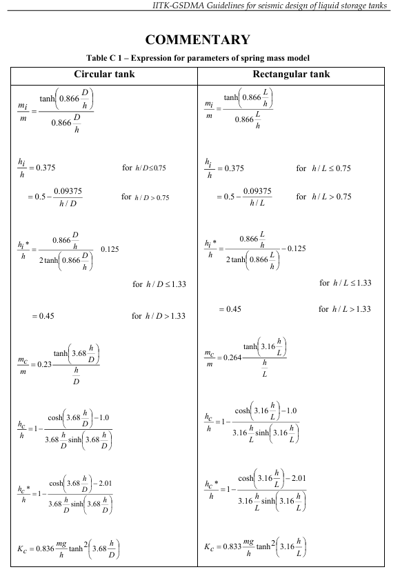
Advanced Seismic Analysis: We incorporated IITK-GSDMA Guidelines to accurately model and account for impulsive and convective modes, leading to precise calculations of increased design moments.
Efficient Workflow: While comprehensive, our approach leveraged formula-based calculations for efficiency, which proved more streamlined than time-consuming FEM setups for defining complex water tank boundary conditions.
Managing Base Uplift: Given the high water table, diligent analysis and design were crucial to mitigate base uplift and integrate the tank’s foundation with the overall load path of the surrounding structure.
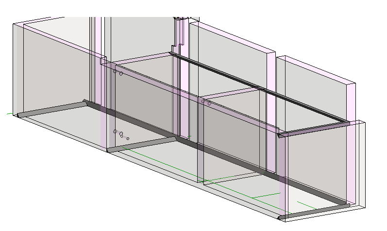
An integrated 3D view of the underground water tank and its adjacent structures, illustrating the overall layout and structural components
Value-Added Deliverables
Beyond core design, we focused on providing comprehensive solutions that streamlined the project lifecycle:
Precise Reinforcement Detailing: We ensured all reinforcement drawings were clear, meticulous, and easy for site workers to interpret.
3D Constructibility Model: A full 3D Revit model with rebar detailing, supplemented by a video, significantly enhanced on-site understanding, minimizing errors and accelerating construction.
Transparent Costing: Early provision of rebar quantities and cost estimates offered the client crucial financial clarity and control.
Key Technical Insights
Our work on this project provided valuable lessons, reinforcing our commitment to thorough validation.
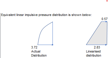
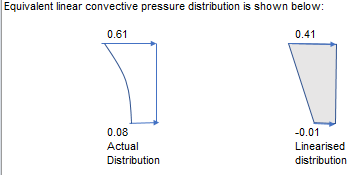
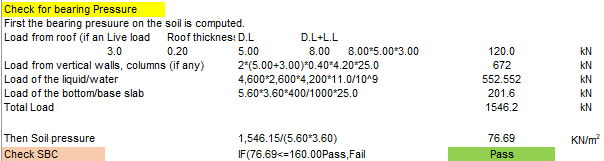
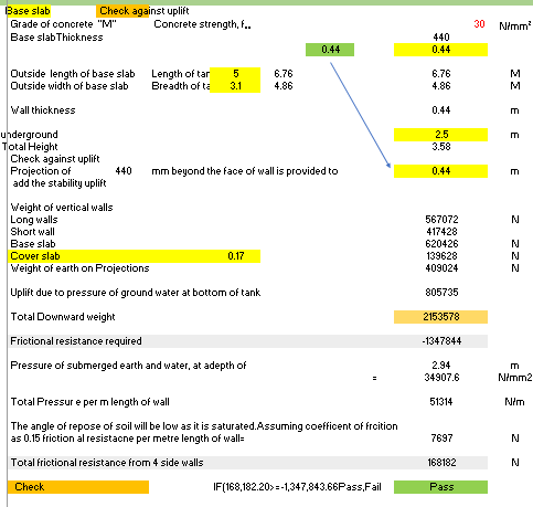
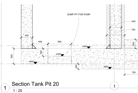
Applying IITK-GSDMA Guidelines for Seismic Design:** This screenshot from IITK-GSDMA EQ 08 (Page 16, Commentary Table C1) illustrates the critical expressions for spring-mass modeling. These formulas (e.g., for mj/m, hi/h, mc/m, hc/h, hkc) are specifically used to determine hydrodynamic forces in both circular and rectangular liquid storage tanks, crucial for accurate seismic analysisDetailed Impulsive Pressure Analysis from spreadsheet: This screenshot displays the calculated curved impulsive pressure distribution on the tank walls, along with its converted linear equivalent for design application. It demonstrates our precise analytical approach to seismic forces.Detailed Impulsive Pressure Analysis from Spreadsheet: This screenshot displays the calculated curved convective pressure distribution on the tank walls, along with its converted linear equivalent for design application. It demonstrates our precise analytical approach to seismic forces.Critical Sloshing Wave Height Calculation: Illustrated here is the formula d max=(Ah)cL2 R used to determine the maximum sloshing wave height. The calculated value of 0.132m is shown to be safely below the freeboard, ensuring containment.Safe Bearing Pressure Verification: This analysis confirms the computed bearing pressure on the soil (76 kN/m²) is well within the allowable Safe Bearing Capacity (SBC) of 160 kN/m² at this depth, indicated by the green highlighted ‘PASS’ cell. Loads from the roof, vertical walls, and liquid are included.This analysis verifies the stability of the 440mm thick base slab against uplift forces, particularly critical due to a high ground water table at 2.5m from the ground level. The calculation incorporates frictional resistance, demonstrating the design successfully passes the uplift criteria Critical Wall-to-Base Slab Junction Detailing: This enlarged section view provides an in-depth look at the complex junction between the 440mm thick wall and the 600mm thick base slab. It clearly illustrates internal haunches, the 900mm wide x 30mm deep sump pit for pump installation, and the increased base depth under specific walls to accommodate higher loads from adjacent building columns and tank length, at an underground elevation of -4600mm.
Download Full Project Details
For a comprehensive understanding of this project’s design and analysis, including detailed drawings and further technical explanations, please download the full 9-page PDF report below.